|
| |
 |
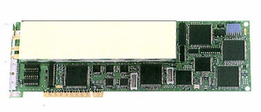
 20 kHz REP.RATE 20 kHz REP.RATE
 5 nsec. RESOL TOF/WT 5 nsec. RESOL TOF/WT
 PCI Plug & Play PCI Plug & Play
 0.5 ~ 20 MHz BW 0.5 ~ 20 MHz BW
 A - B - C / SCAN A - B - C / SCAN
 DLL, DRIVER For WINDOWS DLL, DRIVER For WINDOWS |
| |
| ЧЅНУ
ШИщ Йз ММЦУ ПЙ (click to
enlarge) |
|
|
|
|
| ЛчОч |
| SQUARE WAVE PULSER |
| Voltage |
125/250
Volts (50 Ohms) |
| Fall-time |
5
nsecs |
| Pulse
width |
0.5
to 20 MHz (25 nsecs to 1000 nsecs) |
| Rep Rate |
20
to 20,000 Hz internal trigger, 0 to 20,000 Hz external trigger |
| Probe |
Single
or Dual element |
| Post-trigger |
External
trigger mode |
|
| |
| RECEIVER
/ AMPLIFIER |
| Impedance |
50
Ohms |
| Bandwidth |
0.5
to 20 MHz |
| Gain 1 |
+80
dB |
| Gain 2 |
+80
dB - active after DAC Curve |
| Dynamic
range |
105
dB (0.1 dB steps) |
| Input
attenuator |
0/15
dB (50 W) |
| Attenuator
2 |
0/20
dB |
| Mode |
Echo/Transmission |
| Filters |
0.5
/ 1 / 2.25 / 5 / 10 / 15 MHz & WideBand |
| Rejection |
0 to
50 %, active on A-Scan & Gates |
| RF Output |
2
Vpp. into 50 Ohms (1.5 Vpp. FHS) |
|
| |
| DAC |
| Dynamic |
70
dB |
| Segments |
30 |
| Rep Rate |
Slope |
|
| |
| GATES |
Number |
1
Interface and 2 Flaw / TOF Gates, fully indépendant |
|
| |
| FLAW
/ TOF GATES |
| Threshold |
10%
to 90% (1% steps), 2 symetric thresholds with RF signal |
| Trigger |
Initial
Pulse, Interface, non-active, gate to gate on gate 2 only |
| Start |
60
nsecs to 655mSecs (20
nsecs steps)
0.18 mm to 1,950 mm steel (0.1 mm steps)
0.007 inches to 75 inches steel (0.005 inch steps) |
| Width |
40
nsecs to 655 msecs (20
nsecs steps)
0.1 mm to 1,950 mm steel (0.1 mm steps)
0.005 inch to 75 inches steel (0.005 inch steps) |
| Alarm |
Positive
/ Negative, Number of violation before Alarm : 0 to 30 |
Flaw / TOF
Mode |
Max.
Amplitude or First Echo Amplitude & Alarm
First Echo Depth (peak / threshold / zero crossing) & min
/ max Alarms |
Flaw / WT
Mode |
Max.
Amplitude or First Echo Amplitude & Alarm
In-line Wall Thickness (peak / threshold / zero crossing)
& Coupling / min / max Alarms |
| WT Data
processing |
Upper
/ lower limits, max deviation, Filtering, averaging, etc… |
| Rectifier
Modes |
HW
Pos, HW Neg, FW, RF gating |
|
| |
| INTERFACE
GATE |
| Threshold |
10%
to 90% (1% steps), 2 symetric thresholds with RF signal |
| Trigger |
IInitial
Pulse |
| Start |
60
nsecs to 655 msecs (20
nSecs steps)
0.045 mm to 490 mm water
0.002 inch to 19.65 inches water |
| Width |
40
nsecs to 655 msecs (20
nsecs steps)
0.03 mm to 490 mm water (0.5 mm steps)
0.001 inch to 19.5 inches water (0.02 inch steps) |
| Alarm |
Negative
/ Positive, Number of violations before Alarm : 0 to 30 |
| Rectifier
Mode |
HW
Pos, HW Neg, FW, RF gating |
|
| |
| EVALUATION |
| Rectifier
Modes |
HW
Pos, HW Neg, FW, RF gating |
| Gate
operations |
Flaw
AMP & TOF / Flaw AMP & WT (per Flaw / TOF Gate) |
| AMP
resolution |
1%
Full Screen (0 to 100%) |
TOF / WT
resolution |
0.005 msec (single shot Flaw / TOF
or Flaw / WT mode)
0.01 mm steel
0.0005 inch steel |
|
| |
| OUTPUTS |
| Flaw Mode |
AMP
Analog (8 bit, 0-5 Volts), AMP Alarm (TTL) |
| TOF Mode |
TOF
Analog (8 bit, 0-5 Volts), TOF min / max Alarms (TTL) |
| WT Mode |
WT
Analog (8 bit, 0-5 Volts), WT min / max & coupling Alarms (TTL)
Coupling Quality Analog (8 bit, 0-5 Volts) |
| Interface
Mode |
Coupling
Alarm (TTL) |
| Output
Speed |
Rep
Rate / Timed |
|
| |
| MEMORY |
Real time
acquisition |
A-Scan,
B-Scan & C-Scan data |
|
| |
| A-SCAN
DISPLAY |
| Modes |
HWP,
HWN, FW or RF |
| Gates |
Bars
indicating Start, Stop and Threshold |
| DAC Curve |
Displayed
at midscreen or baseline |
| Range |
1 msec to 1.3 msec (20 nsecs
steps)
3 mm
to 3,900 mm steel (0.1 mm steps)
0.1 inch to 150 inches steel (0.005 inch steps) |
| Delay |
0 to
655 msecs (20 nsecs steps)
0 to
1,950 mm steel (0.1mm steps)
0 to 75 inches steel (0.005 inch steps) |
| Trigger |
Initial
Pulse, Gate 1 trigger, Gate 2 Trigger, Gate 1 Start, Gate 2 Start |
| Displayed
Peak |
True
Max AMP at Rep Rate |
|
| |
| PC
CARD FEATURES |
| Bus |
PCI |
| Board size |
1 /
1 (full) size |
| Subclic
Connectors |
TX,
RX, RF |
| HE10
Connector |
In /
Outputs |
| Internal
Connector |
DSP
bus & multichannel main clock |
| Consumption |
+12
V - 0.5 Amp max. / + 5 V - 1.0 Amp max.
+ 3.3 V - 4.0 Amp max. / - 12 V - 0.1 Amp max.
Total : 25 Watt max. |
|
| |
| SOFTWARE |
| Set
up and Control LabVIEW Software (EXE. & Sources) |
| DRIVER
for WINDOWS |
| DLL
for WINDOWS |
| Driver
performs real-time data transfer to PC memories |
| Inner
card performs Storage & Analysis (DSP) |
|
| |
| MULTICHANNEL
SYSTEMS |
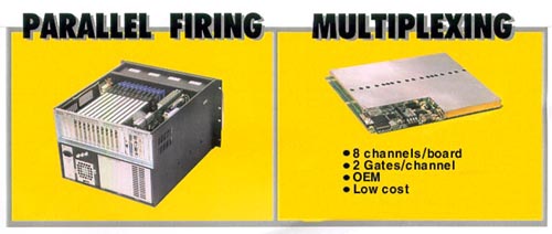
| Parallel
Fire Multichannel Applications |
| Timed
Fire Multichannel Applications (Post-Trigger) |
| Selectable
Firing Sequences |
|
| |
| PC
PENTIUM MIN. CONFIGURATION (One USPC card) |
| Windows
98 |
| PCI
bus |
| Supply
ATX 3.3 volts |
| CD
driver |
|
|

|
|


[Click to enlarge]
|

ST-3000 ЛчПыРк ХЌЗДПЁ АЁРдЧЯИщ
ПЉЗЏАЁСі LibraryИІ АјРЏЧв Мі РжДй.
|
[СжПф ЛчОч]
Ultrasonics
Parameters
· Pulser: Frequency: 0.45 ∼ 20 MHz in steps of 0.05 to 1Mhz
· Receiver: Dynamic Range: 90 dB
DAC: 15 Programmable points
· Gates: Triggering: Positive or negative
Threshold: 10 up to 80% in steps of 0.5%
Acquisition
- A-Scan:
· Test display ·
Transient or maximum signal acquisition
- B-Scan & C-Scan
· N° of gates ·
Amplitude and / or distance (TOF)
· Palette
· Synchro on: · Internal
pulse · Encoder
inputs · Indexer cards inputs
· Scan length-Travel length
· Travel step (pitch)
- Full B-Scan:
· Test display · Transient or maximum
signal acquisition · Colour Palette
· Synchro on · Internal
pulse · Encoder
inputs · Indexer cards
inputs
· Scan length-Travel length
· Travel step (pitch)
Interfacing with bench, manipulators...
· Scan axis selection
· Increment axis selection
· Scan axis speed
· Inorement resolution ·
Scan & travel lengths
- The setting of these parameters is by keyboard and / or by teach &
learn.
Image analysis
· Colour Palette ·Zoom
·Cursor · Histograms (Line X, Column Y, window)
·Cursor indications (Amplitude, Distance, Coordinates)
· Display of X, Y section
Report PRINTOUT
· Colour image with annotated commentary
· Creation of exportable files for EXCEL, LOUTS 1.2.3, etc...
· Additional text with WINWORD

 
Black tubeРЧ ПТЖѓРЮ АЫЛч НУНКХл (4 УЄГЮ); ЕЮВВ
УјСЄ Йз ХЉЗЂ АЫЛч
ЁЁ
 
BarРЧ ПТЖѓРЮ АЫЛч НУНКХл (8 УЄГЮ); Bar diameter: 12 to
50 mm
 
УЪРНЦФ ЗЙРЯ АЫЛч НУНКХл; 32 УЄГЮ, ИЎОѓХИРг ЕЅРЬХЭ
ШЙЕц Йз УГИЎ, B НКФЕ ЧЅНУ, 72 km/h
|
|
 |
|
|
